
Here you will find descriptions of inventions in which I am involved.


Elektrische Brustmilchpumpe:
Inventor: Arndt Last, Invention notification from 26.12.2008.
For pumping breast milk, there are commercial electric pumps that generate a vacuum and suck the milk out of the breast via a silicone adapter. This works rather poorly, because an infant sucks, but at the same time squeezes the milk out of the nipple with its tongue. So a better breast pump should also squeeze the milk out of the breast. This is done here with an eccentric or crank mechanism that rolls a roller along the outside of the silicone adapter. The roller is pressed against the nipple as it rolls away from the breast and away from the silicone adapter as it moves toward the breast. The invention was never registered or realized.
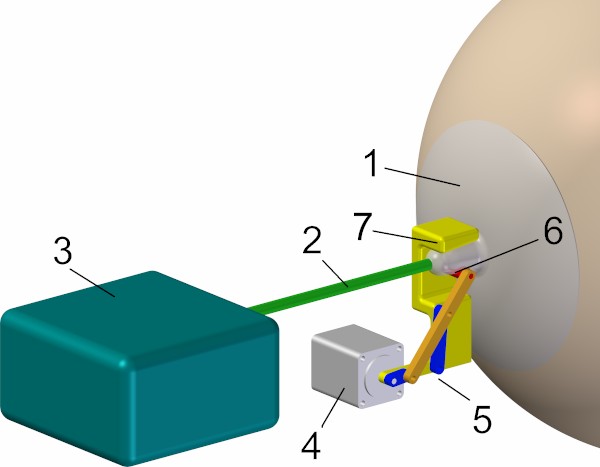
CAD sketch of breast milk pump with silicone adapter 1, suction hose 2, suction unit 3, motor 4, crank or eccentric gear 5, pressure roller 6 and counterpressure plate 7

Animated CAD sketch of breast milk pump
Rocking pram:
Inventor and utility model applicant: Arndt Last, filing date: 15.7.2008, utility model no. DE202008009473U1 "Kinderwagen"
This pram is constructed like a rocking chair: the centre of the circle on which the twelve wheels lie lies above the suspension point of the rocking bed. This automatically returns the pram to the middle position when it is released. Climbing stairs or getting on trains or buses is easy: you simply pull the pram backwards behind you and it glides up the steps along the rear tubes. The frame and the basket are very light, so that you can carry the whole pram. To drive over smaller obstacles such as tram tracks, press the handles of the pram downwards, drive up to the obstacle and lift the handles again when driving over, so that the wheels roll over the obstacle. Actually, the pram was supposed to be foldable. However, it was always used unfolded.
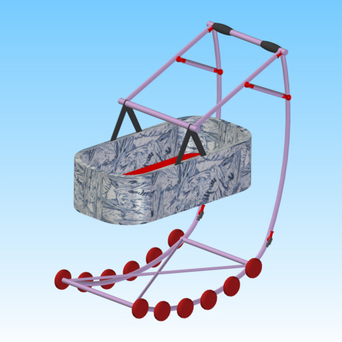
CAD-sketch of the pram
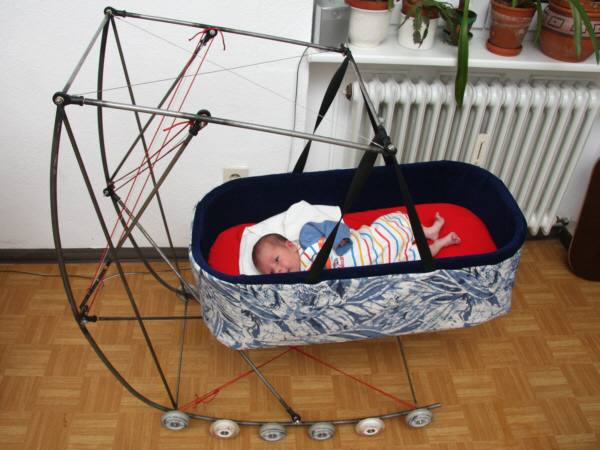
Pram with baby

Infants fall asleep quickly in the rocking pram.
Camera with projector:
Inventor: Arndt Last, 19.5.2008
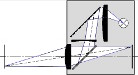
Why do you look at the images of a digital camera on a tiny screen on the back of the camera? If you were to install a projector in the camera, you could project the captured images through the lens of the camera onto any projection surface, such as a white wall. You can also use the autofocus of the camera at the same time. With SLR cameras, even the necessary 45° deflecting mirror is already present. Today, the light intensity of a battery-powered projector limits the maximum possible size of the projected image. With increasing luminous intensity of light emitting diodes such a camera projector will find distribution.
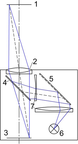
Beam path in a camera that also serves as an image projector with projection surface 1, recording or projection lens 2, digital detector 3, folding deflecting mirror 4, image-generating chip 5, light source 6 and projection optics 7
Foldable bicycle "Chi":
Inventor: Arndt Last, 04/2008
The folding bike "Chi", named after the shape of its frame, won first place in the "Car Dinghy" international ideas competition organized by the "Future Bike CH" association. In a car, it fits into the space normally occupied by the spare wheel. Since the distance between the front wheel and the driver's centre of gravity is small, the braking characteristics of the folding bike would not be very good. Since it would also be difficult to make the frame stiff enough, I didn't build the bike.
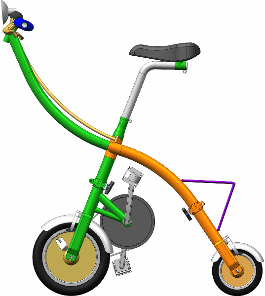
CAD side view, 04/2008 
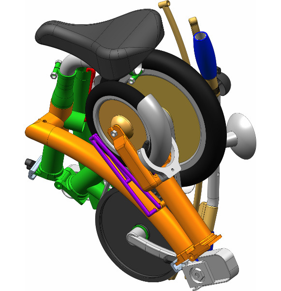
Another CAD-view, 04/2008

This is what it would look like with a driver, 04/2008
Micro positioning system:
Inventors: Christian Solf, Arndt Last, filing date: 23.4.2005, Patent no. DE102005018955B4 "Mikropositioniersystem"
This micropositioning system works according to the so-called 'inchworm' principle: If a voltage is applied between one of the two flat electrodes 1 and 2 and the electrode 7, the respective electrode is pressed against the substrate and cannot move. If the two electrodes are fixed alternately and the opposing electrode is moved, the actuator moves forward like an inch worm. The distance between the two flat electrodes 1 and 2 decreases when a voltage is applied between the two interdigitated electrostatic comb actuators 4 and 5. The elastic plastic ring 6 is deformed so that the actuators move apart again when no voltage is applied. With suitable geometry, the actuator can also move in different directions or rotate around an axis. The micropositioning system is suitable for production using the LIGA process with sacrificial layer. These actuators have not yet been realized.

View of the actuator with adhesive electrodes 1 and 2, electrode 3, comb structures 4 and 5, polymer spring 6, substrate 7 and dielectric 8
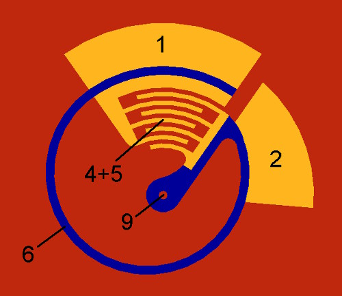
Variants of the micropositioning system: rotary actuator with rotary axis 9 and as 'mouse-over" actuator with two directions of movement perpendicular to each other
Portable printer with rotary printhead:
Inventor and utility model applicant: Arndt Last, filing date: 2.12.2003, utility model no. DE20318595U1 "Tragbarer Drucker mit rotierendem Druckkopf"
A single-sheet printer can become very small when the sheet of paper to be printed is rolled and then printed. The printing speed can be higher than with a standard inkjet printer, where the print head must change direction after each printed line. In the rotary printer, the rotation speed of the print head is constant, the paper feed takes place in the time it takes for the print head to move from one edge of the paper to the other. The machine could also hold two sheets: an original to be scanned and a blank sheet to be printed with the copy at the same time. If you lift up an inkjet printer during printing and rotate it in all directions, the print is not worse: a rotating inkjet printhead should be feasible.
CAD-view of the printer with the housing cut open.
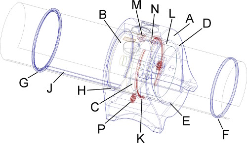
Sketch of a possible appearance of a printer with rotating print head with housing A, print head B, motor C, insertion aid D, paper insertion slot E, rings F and G, exit slot H, rods J, brush ring K, guide cylinder L, rollers M and N, pressure roller P
For printing, a ring F is pushed over the paper, then the paper is placed on the edge D, which serves as an insertion aid, and pushed into the paper guide slot E. The paper is then fed into the paper guide slot E by means of pressure rollers P and feed rollers N and M. With the aid of pressure rollers P and feed rollers N and M, the paper is guided past the rotating print head B and pushed into the collecting ring G on the back of the housing, from where the finished print is removed. A DIN A4 printer can have external dimensions of 12 cm Ø x 8 cm, a DIN A3 printer can have external dimensions of 16 cm Ø x 10 cm.
Meanwhile the company Samsung put pictures of such a printer into the net. Ten months after my utility model DE20318595U1 "Tragbarer Drucker mit rotierendem Druckkopf" from 2.12.2003 they got the US-Patent US7441969B2 "Portable printing apparatus having cylindrical paper path between inner and outer cases" from 9.10.2004.
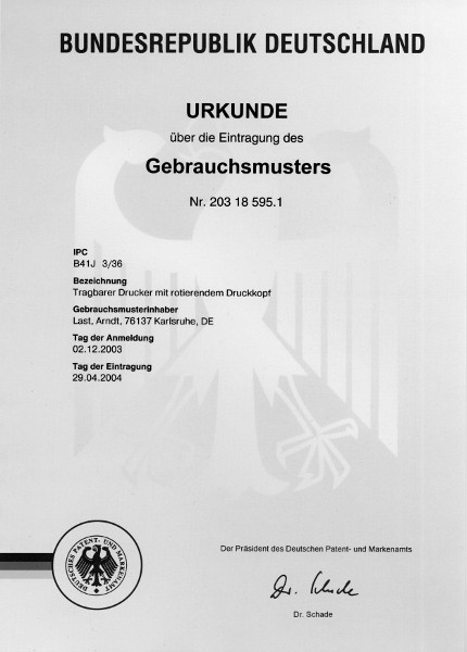
Utility model certificate DE20318595U1 "Tragbarer Drucker mit rotierendem Druckkopf" from 2.12.2003
Chain differential for multi-track bicycles:
Inventor: Arndt Last, Frühjahr 1989
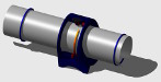
If both adjacent wheels of a multi-track bicycle are to be driven, the installation of a differential gear is a good solution. Such a differential gear automatically distributes the drive power to both wheels, with the faster wheel receiving more power. This means that the cadence does not become uncomfortably low even in tight corners. Conventional differential gears use bevel gears, which makes them expensive and requires precisely aligned gear bearings. This makes them difficult to use in bicycles. Such a differential gear can also be constructed exclusively from bicycle sprockets and bicycle chains:
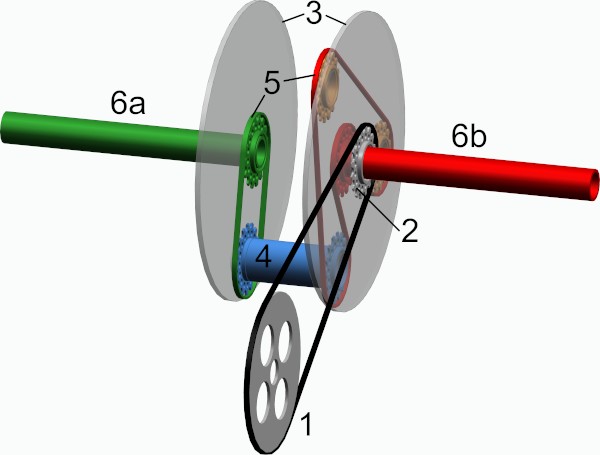
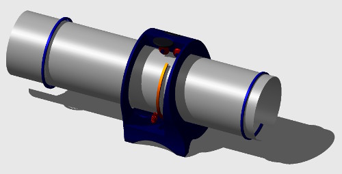
The chainring 1 driven by the pedal cranks drives the sprocket 2, which is rigidly connected to the grey gear housing. The two sides 3 of the gear case are rigidly connected to each other, the connection is not shown here. The blue shaft 4 is connected to the housing and carries two sprockets. The two chains 5 transmit the forces to the individually pivot-mounted half-axles 6a and 6b, which lead through the housing walls to the wheels. The two orange sprockets deflect the chain in such a way that the wrap angle of the red and blue sprockets is as large as possible. The sprockets do not need to be aligned as precisely as gear wheels, as the chains compensate for misalignments. The components are inexpensive and the gearbox can also be built by hobbyists. If you use sprockets with 12 teeth, the cage diameter will be about 200 mm and the width about 30 mm (in the drawing the housing is too wide to be able to look inside). If the sprocket 2 contains a freewheel, the possibility of a reverse gear is lost. Instead, the two sprockets drawn in orange can be small 10 teeth plastics deflection rollers, because in this case the gear chain is only loaded directly between the sprocket drawn in red and blue. The construction can be made much narrower than in the picture and allows a stiff construction also from single stiff struts between the axles 6a and 6b instead of a complete cage. In order to avoid imbalance, it may be necessary to balance the gearbox.
Hinged cover for optical waveguide microstructures:
Inventor and utility model applicant: Arndt Last, filing date: 21.1.2003, utility model DE20300841U1 "Klappdeckel für optische hohe Wellenleiter-Strukturen"
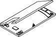
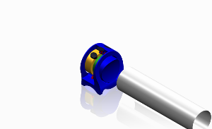
Microoptical components such as microspectrometers or distance sensors are sometimes constructed as hollow waveguides. This means that the light is guided in them by reflection between two reflecting surfaces. Previously, such waveguides were manufactured from two parts and then assembled. If the optical component and the cover of the waveguide are manufactured as one part, with the two halves connected by a hinge, this has the following advantages:
- You only need one tool.
- After closing the parts are automatically positioned to each other.
- Both halves have the same surface quality and can be mirrored together.
- The lid needs less adhesive dots, because one side is already fixed by the hinge.
This process has not been used in production so far on the explanation that the conversion of the tool shop is not worth the effort.

Micro spectrometre with hinged lid, open
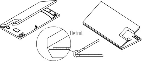
Micro spectrometre with hinged lid, half-closed
Bending template for electronic components:
Inventor: Arndt Last, Patent holder FZK, Karlsruhe, filing date: 8.6.1998, Patent no. DE19825551C1 "Biegeschablone für Elektronikbauteile"
The electronic component is inserted with one leg into the hole in the template and bent twice to the desired pitch (1/10 inch steps) so that it can then be inserted through a perforated circuit board and soldered. The tool is flatter than previous tools and can be carried in the trouser pocket. I built a copy for my own use, no marketing took place.

The three steps of the bending process: insert a wire and bend it twice.