


Canon zoom lens EFS 17-85 mm mechanically blocked
With the Canon lens EFS 17-85 mm it happens that the zoom ring can no longer be moved or only over a part of the zoom range. This severely limits the zoom range of the lens. Sometimes only "Err 99" or "999" flashes in the camera's LCD display and the camera no longer fires. When no lens is used or with a good lens the camera will release again if you turn it off, remove the battery, reinsert it, and turn the camera on again. This is caused by three screws inside the defective lens that are not properly secured against unscrewing. Since it's not worth sending the the objective in for repair for about 150 €, here's a guide on how to fix the problem yourself. The manual is based on the Travis Hydzik manual. I assume no liability for the consequences of an attempt to repair a lens according to these instructions. An English manual for repairing another error of this lens (blocking the aperture) can be found here.
The lens looks like this before it is repaired:

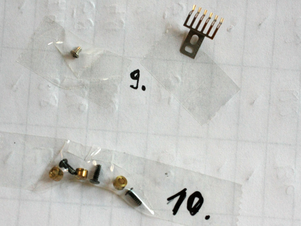
It is best to leave a protective filter on the lens to avoid fingerprints on the front lens. Work in a clean environment to prevent unnecessary dust from entering the lenses. Avoid fingerprints on the lenses: they are difficult to remove without damaging the lenses! Follow the instructions and do not loosen any other screws or the like. Only start the repair if you have the necessary four hours in a row to do so. If you can continue only days later, the probability that you will get the lens reassembled decreases according to experience. I recommend that you carry out the repair on an otherwise empty table and place a large sheet of white paper underneath so that you can quickly find any parts that have fallen off. I carefully glue all the parts I remove onto another sheet of paper with adhesive tape and number them so that I know later which part needs to be reinstalled next:
Disassembly of the lens
To reach the loose screws, several parts and about 20 screws have to be removed. First, on the bayonet side, two Phillips screws are turned near the gold contacts from the bayonet socket:

It is useful to place a black line with a permanent marker in the position visible in the picture so that you know how to align the parts when you assemble them. Next, remove four screws:

Now the metal ring on one side can be folded away slightly. Caution: It is still connected to the lens via a cable strap! Do not open wide:

A black plastic ring is clipped into the metal ring. The black plastic ring has to be detached from the metal ring. To do this, you have to bend the plastic clip through the gap and without damaging the cable strap until you can push the plastic ring through the metal ring towards the outside of the lens. It is best to hold the lens in one hand and the metal ring between thumb and index finger of the same hand. With the other hand, you can bend two of the four clip springs away from the metal ring with the help of a fine screwdriver or a blade through the gap until the plastic ring can be pushed through the metal ring. This step is a bit tricky.

Here pictures after loosening the plastic ring:


The contact strip with the gold contacts can now be easily removed from the metal ring, then the ring can be lifted off and put aside.

The black part of the case below (with the slide switches AF/MF and stabilizer: on/off) can only be lifted off when a ribbon cable is disconnected from the board. I have labeled the cable "A" here. It can be pulled out of the plug with the help of a screwdriver, which is inserted alternately into the two rectangular recesses in the white area of the cable. After lifting off the housing part, do not change the position of the slide switches any more so that they fit again later during assembly.

After lifting off the black part of the housing, four more cable connections become visible. I recommend to label the cable tapes and the corresponding plugs in the same way. The four cable connections must be loosened. Remove the plugs labeled "B" and "C" like plug "A" by pulling out the cable.

The plug labeled "D" by me has two small black sliders on the side. Pull these sliders carefully in the direction of the cable out of the plug before you can remove the cable:


With the plugs I labeled "E" and "F", fold up the pressure flap, then the cable strap is loose in the plug:


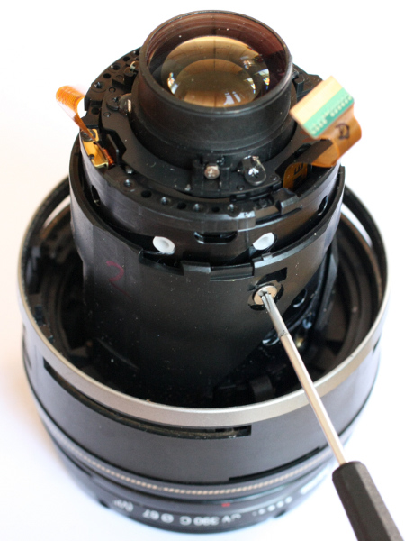
Now loosen the screw marked at the top of the picture, which fixes the PCB. Remove the circuit board. In the plane below you have to loosen eight screws. The first five hold another black plastic ring, they are marked red in the next picture:

The ring only fits on the lens in one position. Nevertheless, it is practical to mark the relative position between the inner part of the lens and the ring with a marking line. Remove the ring. Now remove the next three screws:

Next, remove the rubber sleeve. To do this, place a thin screwdriver or a blade under the rubber and loosen it from the lens over its entire circumference, then wipe it off.

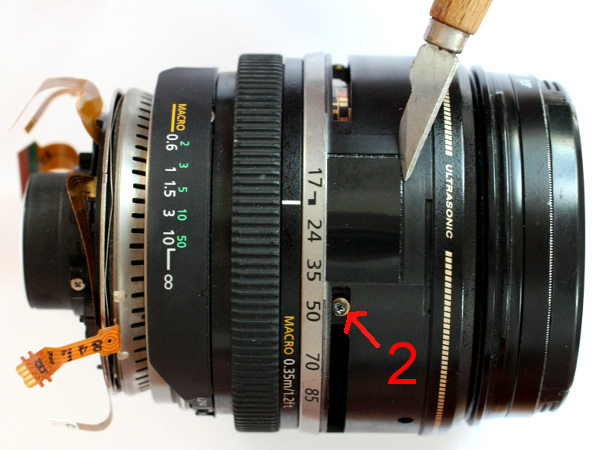
For easier assembly, draw a black line over all parts so that the alignment of the parts remains clear. Reference is made to the figure "2" in the picture below.

Now carefully remove the rectangular black sticker near the "17 mm" focal length mark. The sticker covers a hole in which sliding contacts can be seen. It will be attached again later, so do not dirty the adhesive side. The mark "2" in the picture is used as a reference in the text below.
In some cases, a small screw or a broken plastic part can stick to the adhesive side of the sticker: Parts that have come loose inside the lens! Don't lose it!

Unscrew the sliding contact at 1 and carefully put it aside (see also second picture from above, "9."):

There are three screws (marked "2" in the illustrations) which are inserted in a guide slot in brass sleeves. Remove these three screws (see also second picture from above, "10."). It is best to remove the brass sleeves together with the screws, otherwise one will easily fall into the interior of the lens. But that doesn't hurt either, because you can find them there right away. Now you can lift off the upper part:

Removal of the blockade
The cause of blocking is usually three screws on the side of the lens tube, which are not properly secured against loosening. Before tightening the screws, make sure to secure them against loosening again with a tiny amount of two-component adhesive on the thread. It is not sufficient to place nail varnish next to the screw head, as the forces on these screws are too great.
Another reason for a jammed lens can be a guide claw whose two fixing screws have come loose. This error occurs less often, but I will describe how to fix it here anyway. If the guide claw is fixed, you can skip the following steps and start assembling now. In addition, a small plastic stop (there are two of them), in which the guide claw engages, was broken (one of the screws and the plastic nose stuck to the adhesive side of the foil, which covered the hole over the sliding contacts, see picture above). First, glue the plastic stop with two-component adhesive ("Uhu plus sofortfest").
To get to the place with the guide claw, grasp the top edge of the lens in the pictures and pull it all the way up (possibly turn the tube underneath slightly counterclockwise when seen from above):

Screw in the two screws holding the guide claw again and secure their threads with two-component adhesive beforehand:

In the event that a plastic stop has broken off, as in my case, lift off the ring on which the focal length details are printed:

Now you can see the guide stops on the inside of the focal length ring and, if necessary, degrease the spot with alcohol and stick the nose - if you have found it - back on again:


The remaining nose is pretty worn out.
Reassembling the lens
The assembly is of course done in reverse order, but some points should be mentioned to make the assembly easier. Screw on the ring with the focal length specifications so that the focal length label "85 mm" is almost exactly opposite the guide claw when the inner structure is pushed together with the lenses. The outer focal length ring has three narrow guide screw grooves on the inside. It consists of the part with the focal length marking and of a ring extension, which serves as dust protection. First you pull these two rings apart (possibly fix them with adhesive tape so that they don't slip together again and again), then you thread the extension ring with its inner grooves over the narrow felt dust seal on the outside of the part with the lenses so that the three short pins are above the felt seal (in the next picture two of the three pins are marked with a green arrow) in the guide grooves.

Then adjust the ring with the focal length marking (remove the adhesive tape again!) and the tube with the lenses so that the guide claw is in the middle of the two plastic stops and the whole thing is again in the pushed together position.

Next, slide the ring with the ultrasonic motor and the flat ribbon cables over it so that the guide fork marked with a red arrow in the next picture engages centrally over the guide pin with the green line on it (marked with a red arrow on the left in the penultimate picture). Handle the ribbon cables very carefully when threading them through so that they are not bent!

Turn the ring in the picture above so that its position corresponds exactly with the one at the top of the picture. It then snaps in a little and can hardly be twisted anymore. Do not pinch any ribbon cables! Tighten with the three screws.
Screw in the three screws with the brass sleeves. Always turn the screws with the sleeves from below into the objective so that they do not fall inside if they slip. Next, insert the black ring with the four raised structures. First thread the longest ribbon cable in the middle, then bring the one marked "D" into position, then thread "E" and "F" from the inside through the windows in the ring. Ribbon cable "B" remains outside the ring. Fix the ring with five screws. Put on the printed circuit board and fix it with a screw. Fix the ribbon cables "B" to "F" in their plugs. At "D" press in the sliders alternately right and left until both are tight.
Place the ring with the AF/MF switch so that the distance scale can be seen in the viewing window. Do not forget the ring for the manual distance adjustment (if it has fallen off at all) and install it the right way round: on its inside there are rectangular cut-outs which have to fit into corresponding opposing rectangles. Insert the plug "A" through the holes in the top black plastic layer into its plug. Screw on the metal ring with four screws. Clip the strip with the gold contacts onto the edge of the metal ring and fix it with two small screws. Finally, carefully press on the ribbed smaller black ring from above and snap it into place.
Congratulations, when the lens works again!
Broken screen at digital camera Panasonic DMC-TZ7
A broken screen (display) of the digital camera Panasonic DMC-TZ7 can easily be replaced. I ordered the replacement screen over the Internet for 42 Euro. There you will also find a video of the repair of a similar device. In the film, the repair only takes five minutes: take an hour, as this is the first time you have done it. The individual steps are documented here again with photos. This is how the camera looks from the front:

And so the broken screen turned on:

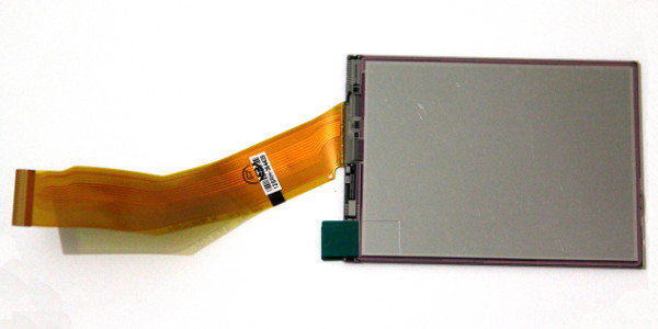
The spare part is ready  :
:
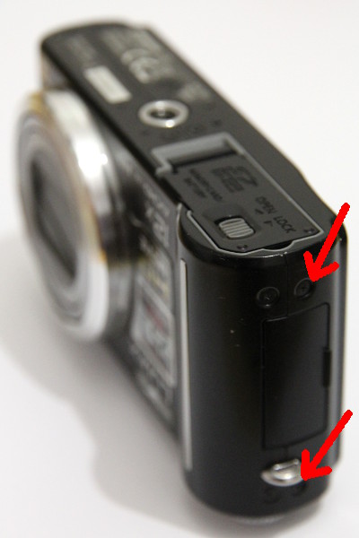
First remove the battery and only then open the housing. To do this, loosen the three screws on the screen side of the base plate:

Unscrew three more screws on both sides of the camera. The screws are all the same, so there is no danger of confusion.

The rear panel can now be removed, but is still attached to two ribbon cables.
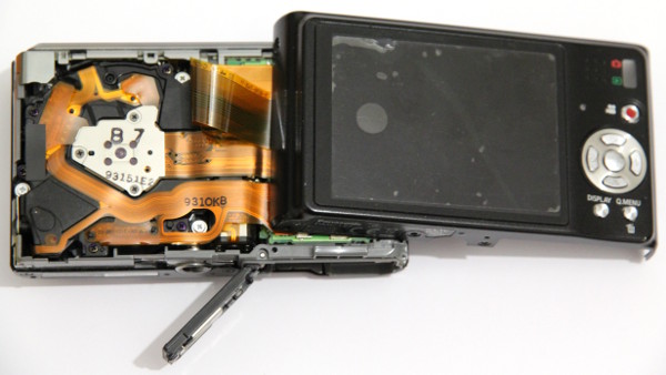
If you put the rear panel to the left on the other side, you can see the connectors of the ribbon cables:

The two flat ribbon cables can only be pulled off when the narrow black terminal strips have been flipped up. To do this, carefully lever up the strips with your fingernail, coming from the direction of the arrow in the picture. Then pull the ribbon cables to the left.

So the old screen is in the back of the case:

The display unit is snapped into place at three points on the back of the housing. The latches can be released by pressing with a small screwdriver from the outside into the openings (arrows in the picture) (i.e. against the bare metal arms of the screen holder) and at the same time pressing lightly against the screen from the outside of the camera.

On the opposite side, the screen cassette is only hooked in (three arrows in the next picture), there is nothing to do here. If the handles in the picture above are released, the unit can be removed.

Next, open the screen cassette. There are four jacks, two of which have to be opened on one side. This requires a bit more force.

The cassette splits into half with the screen and the other half with the screen backlight (with the narrow ribbon cable):

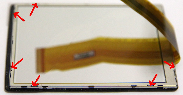
Next, remove the thin, delicate metal frame that attaches the screen to the back of the case. Either use strong fingernails at the points marked with arrows to open the handles or use a fine blade. Be careful, the frame deforms easily.
Now the screen can be separated from the rear wall. In order not to do anything wrong later during assembly, you can mark the three parts at one corner (here with a "1").

If necessary, clean and dedust the window in the back of the housing. For the replacement screen, first remove only the protective film on the black side. Place the thin metal frame on the shiny back of the screen (the green sticker for removing the protective film must be over the frame) and place the screen in the socket on the back of the housing.

Carefully snap the thin metal frame into place without bending the screen:

Peel off the second protective film and clip the screen frame back together with the frame of the backlight. Do not bring in any dust or fingerprints. The whole unit can be inserted into the back of the housing and pushed down to snap into place:

Push the ribbon cables into the plugs and fix them by turning over the narrow black clamping strips. Place the rear panel of the housing on the camera and tighten the screws again. Congratulations, when the camera works again!

MP3-Player Cowon iAudio U3
The mechanical stability of the audio output socket and the buttons of this otherwise very sonorous MP3 player is too low. This section describes how to repair the device if the sound is lost due to a loose contact in the audio output socket. It also describes how to correct the failure of individual buttons.

First, unscrew the four screws on the back of the device: the screws are relatively long, use the right screwdriver.

Open the housing in the joint between the grey, surrounding strip and the front of the device. There are several jacks which hold the case halves together. With a little wobbling, they can be released easily.

Next loosen the plug connection of the battery with the main printed circuit board. Slide out the corners of the transparent connector part in the direction of the red arrows with a small screwdriver or similar:

Then loosen the two screws holding the printed circuit board (see red arrows two pictures above). One of the four tubes on the case, into which the four case screws are turned, was broken off and broken in length. I did not repair this part, because three screws ar eenough to hold the case together:

Then carefully bend the four white handles that hold the display open and flip the display away.

At the red arrow in the next picture, fold up the narrow, black flap (see also last picture below): this releases the foil cable.


Plug connection of the display; with the mouse over the picture you can see the connection with the clamp connector flipped up.
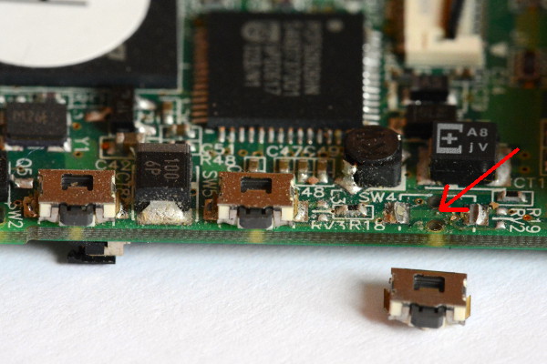
Now the button of the "REC" button can be re-soldered, which was loose in the device. .
If you don't have a small enough soldering iron at hand, you can wrap a copper wire around the tip of the soldering iron and use the end of the wire as a fine soldering tip. The thermal conductivity to the wire is better if you put solder between the tip of the soldering iron and the wire.

The loose contact of the audio output was created when the error first occurred because the solder joint between the connector housing and the circuit board did not withstand the mechanical loads. Soldering solved the problem. At the second occurrence two years later, two cracks appeared on the right and left side of the solder joint (see picture below ).

I just made the solder joint wider, will hold again a while:

When assembling, only the insertion of the display cable is a bit fiddly. First fold up the narrow, black clamping strip (red arrow 1 in the next picture), then thread the foil cable into the guides 2 and push it vertically as far as it will go and finally fold down the clamping strip again without the cable slipping out.

Congratulations when the MP3 player works again!
Clean notebook fan
My notebook from the company "mysn", model "XMG P501 Pro" (on the back of the device is the manufacturer "Clevo Co., Model P150HM") with i7 processor and four 'double-thread' cores simply switched off when CPU-intensive tasks were being performed. If the two fans are permanently switched on with the key combination 'Fn'+1 (switched off with the same key combination; this function is not documented), this no longer happened. So the fans probably have to be de-dusted. Disconnect the device from the mains adapter, remove the battery as a precaution. Loosen the four screws of the large cover on the underside of the device.

Then move the lid backwards along its short edge and remove it.
The two fans become visible.

Unscrew the four screws of each fan cover.

The air outlet slots are largely blocked, and the fan wheel is also dusty.
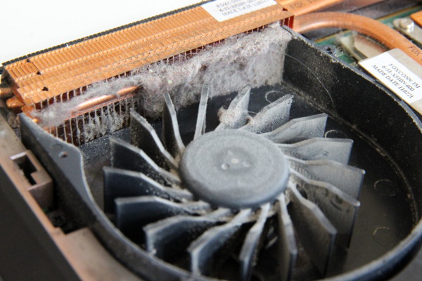
Remove the dust. When using a vacuum cleaner, hold the fan wheels as a precaution so that the fan does not become a generator and feeds voltages into the unit that could cause damage. I used ear cleaning sticks soaked with window cleaner (do not drip drip into the device!). Reassemble the device. The error no longer occurs and the device is quieter than before.

Congratulations on your dedusted notebook!
Repair sewing machine Gritzner exclusiv 976
The manual isn't finished yet.
Mechanical sewing machines all function similarly and can usually be repaired. Sometimes the machine is only very dusty inside and must be thoroughly cleaned and oiled. Sometimes screws are loose, so that something has misplaced itself. And sometimes a plastic part or gear is broken. If there is a spare part, the broken part can be replaced. Maybe you can also rebuild the part and replace it. Here is the description of a "Gritzner exclusiv 976" household sewing machine that had to be overhauled because the needle was no longer up or down at the right moment and because the needle was no longer pulled to the left fast enough when sewing zigzag seams faster. The following disassembly instructions are intended as a suggestion. Only open a sewing machine unpluged from the power net and only if you are confident that you can repair it. If you loosen parts, it is advisable to mark both parts beforehand with a foil pen so that you can bring the parts back to the old position in case of doubt. Take pictures of all disassembly steps and tape the removed parts and screws onto a piece of paper and number them to make assembly easier later. The machine looks like this:

Disconnect the mains plug before carrying out any work so that the machine is voltage-free. If the machine does not start, first check whether the fuse in the foot pedal has blown. This can happen, for example, if the light bulb blows. Replace the fuse and the machine is ready to go again!
All directions given in the following refer to the picture above. For example, "pull to the left" means "pull away from the handwheel and along the longitudinal axis of the machine".
To disassemble the machine, first remove the cover on the head section. Two screws must be loosened for this. One is at the top of the rectangular hole, the second is accessible from below (very short Phillips screwdriver!), both only have to be loosened:

Now the cover can be pulled off to the left and the bulb can be changed easily (unfortunately there was no bright LED replacement bulb in 2012 to replace the permanently broken bulb).
The first error that the needle is not pulled quickly enough to the left when sewing zigzag seams faster and that not all stitches are in the right position can now be corrected. In the guides B, the oil is resinified and the carriage no longer moves in the guide. Remedy: Clean the guide with benzine (be careful with the plastic parts nearby!) and re-oil it with sewing machine oil. If this is not enough, you can remove the spring from the hole at A and hook it back in under the bar (see mouse over it!). This makes the spring a little stronger and the needle is pulled to the left more quickly. Even if this is not enough to increase the tension sufficiently, the last remedy is to glue a spacer between the spring and the pin above which the spring is suspended. Shortening the spring by bending it is risky as it can break easily.
 Guide carriage at B and spring suspension at A
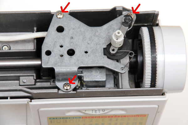
After loosening the two screws under the carrying handle of the machine the upper cover can be lifted upwards.

If the three screws underneath are loosened, the sheet can be lifted up with the thread bobbin device.
Below this is the worm gear, which drives the cam disk control of the stitch selection. The worm is fixed to the shaft with grub screws. If the worm is loosened, twisted and screwed tight again, the point in time at which the needle changes its position in the right-left direction changes. If, for example, the needle is first dipped into the fabric and then shifted sideways, this can be corrected here. The needle may only change its lateral position near the highest point.

The cover under the upper arm of the machine does not hide much, but can be removed by removing two screws under the upper cover (next picture) and one screw next to the lamp (next but one picture). To do this, the lever that lowers the transport foot must be at the bottom and threaded through the hole in the cover. The cover is folded down on the lamp side and then pulled to the left.
1. IMAGE missing

The base plate is bolted with four long metal screws.

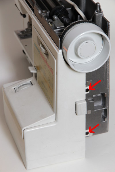
The cover with the power connector is snapped into the front right cover with four pawls, two on the side with the power switch and two on the other side. These pawls must be carefully bent open so that they do not break. The cover can then be pulled back.


The front cover is clamped with four screws, these only have to be loosened, then the front cover can be pulled off to the front.
XXX: Text unfortunately unfinished.
Congratulations on the repaired sewing machine!